You're staring at a tiny chip on a circuit board. There's a cryptic code printed on it maybe two or three characters and you have no idea who made it or what it does. This happens to almost everyone who works with electronics, from hobbyists fixing a motherboard to engineers sourcing replacement parts. Knowing how to read maker codes on electronic components saves you time, prevents ordering the wrong parts, and helps you trace components back to their manufacturer for datasheets and specs.
What are maker codes on electronic components?
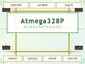
Maker codes are short alphanumeric markings printed or laser-etched onto electronic components. They identify the manufacturer of the part not necessarily the part itself. A maker code is different from a part number. For example, a component might have the part number "LM7805" along with a separate maker code like "TI" (Texas Instruments) or "STM" (STMicroelectronics).
On larger through-hole components, you'll often see full manufacturer logos and part numbers printed clearly. But on surface-mount devices (SMD), space is extremely limited. That's where maker codes become abbreviated sometimes just one, two, or three characters squeezed onto a package that's only a few millimeters wide.
These codes fall into a few categories:
- Logo marks graphical symbols representing the manufacturer (like the Motorola "M" or the ON Semiconductor checkmark)
- Alphanumeric shortcodes abbreviated letters and numbers, such as "NE" for NEC or "IR" for International Rectifier
- Date codes and lot codes indicating when the batch was manufactured, often following the maker code
- Country-of-origin marks sometimes present alongside maker codes
Why do maker codes look so different from one component to another?
There's no universal standard for how a manufacturer marks their parts. Each company has its own conventions. Some use a single letter, others use a two-letter abbreviation, and others use a stylized logo that barely fits on the package.
Component size matters a lot. A large electrolytic capacitor might have room for a full company name and part number. A tiny 0402-size resistor has room for almost nothing sometimes just a single character or even no marking at all. As packages have gotten smaller over the years, many manufacturers have moved to laser-marked codes that are faint and hard to read without magnification.
Different eras also used different conventions. Older components from the 1980s and 1990s often had bold, clearly printed codes. Modern components tend to use subtler markings. If you're working with vintage electronics or salvaging parts from old boards, the marking style might look unfamiliar compared to current components.
For a detailed reference of common shortcodes and their manufacturer matches, our SMD component maker markings reference chart is a useful lookup tool.
How do you actually read a maker code step by step?
Reading a maker code is part observation, part research. Here's a practical process:
- Examine the component under magnification. Use a loupe, magnifying glass, or USB microscope. SMD codes are often laser-etched and nearly invisible to the naked eye. Good lighting at an angle helps.
- Record every marking you see. Write down or photograph all text, numbers, logos, and dots. Don't assume anything is decorative dots and lines often carry meaning (like pin-1 indicators or polarity marks).
- Separate the maker code from the part number. The maker code is usually shorter. On many components, the maker code appears first or is positioned near a logo. The part number or ordering code follows it. For example: "ON" followed by "LM358D" tells you ON Semiconductor made this LM358 op-amp in an SOIC package.
- Look up the shortcode in a manufacturer database. Cross-reference the characters with known databases. Common two-letter codes include:
- NE NEC
- ST STMicroelectronics
- NS National Semiconductor (now Texas Instruments)
- FA Fairchild (now ON Semiconductor)
- IR International Rectifier (now Infineon)
- Verify with the datasheet. Once you think you've identified the manufacturer, find the datasheet for the part number and confirm the package type, pinout, and specifications match what you're seeing on the board.
Our full walkthrough on reading maker codes goes deeper into this process with more visual examples.
What do the extra numbers and letters after the maker code mean?
After the maker code, you'll often see additional characters. These aren't random. They typically encode useful information:
- Date code Usually a four-digit number representing year and week of manufacture. "2345" means the 45th week of 2023. Some older formats use a single digit for the year and two digits for the week.
- Lot code A batch identifier used for traceability. If a defect is found in production, manufacturers can recall parts by lot code.
- Country code Sometimes indicated by a letter or abbreviation, showing where the wafer was fabricated or where final assembly happened.
- Assembly site code Larger manufacturers with multiple factories use single characters to identify the specific facility.
For example, a marking like "TI 2334 MALAYSIA" tells you Texas Instruments made this part, it was produced in week 34 of 2023, and it was assembled in Malaysia.
What are the most common mistakes people make?
Misreading maker codes is easy, and it leads to ordering the wrong replacement parts or misunderstanding a circuit. Here are frequent pitfalls:
- Confusing the maker code with the part number. "ST" on a chip doesn't mean the part number starts with "ST." It means STMicroelectronics made it. The actual part number follows separately.
- Misreading damaged or faded markings. Heat, age, and chemical exposure can blur codes. A "B" might look like an "8," or a "5" might look like an "S." Always cross-check with the circuit context.
- Assuming all makers use the same format. Texas Instruments uses "TI," but they also sometimes use just the letter "T" or their older National Semiconductor code "NS" on legacy parts. Mergers and acquisitions make this confusing Fairchild parts now carry ON Semiconductor codes.
- Ignoring date codes when sourcing parts. A component made 15 years ago might have degraded, especially electrolytic capacitors and certain ICs. The date code helps you assess freshness.
- Overlooking logo marks. Some manufacturers don't use text codes at all just a small graphical logo. Learning to recognize these logos (like the Philips shield or the Rohm "R") is just as important as reading text codes.
How do you identify maker codes on SMD resistors and capacitors?
Passive components like resistors and capacitors are a special case. They're often too small for any maker code at all.
SMD resistors in 0603 and larger sizes sometimes show a resistance value code (like "472" for 4.7 kΩ) but rarely show a maker code. The manufacturer is typically identified only by the packaging tape, reel label, or purchase documentation. Smaller sizes (0402 and below) usually have no marking whatsoever.
SMD ceramic capacitors are almost universally unmarked. You can't read a maker code off them because there's nothing printed on the body. You rely on the supplier's documentation and the reel packaging.
For resistors specifically, we have a dedicated resistor maker code identification guide that covers value codes, tolerance bands, and how to figure out who made the part.
Can fonts or text style help you identify the maker?
Sometimes, yes. Experienced technicians learn to recognize the typeface and printing style used by different manufacturers. A particular font weight, character spacing, or laser-etch depth can be a clue. Japanese manufacturers like Rohm and Murata tend to use clean, precise printing. Some older American manufacturers used heavier, bolder characters.
This is similar to how OCR Font styles are designed for machine-readable text manufacturers sometimes use simple, unambiguous typefaces so automated optical inspection systems can read the codes reliably. Recognizing these patterns takes time and exposure to many components, but it becomes second nature.
What tools and resources actually help?
You don't need expensive equipment, but a few things make the job much easier:
- USB digital microscope Costs around $20–$40 and makes tiny SMD codes clearly visible on your computer screen. Far better than squinting through a loupe.
- Good overhead lighting Angled light reveals laser-etched markings that flat lighting misses. A small LED desk lamp works fine.
- Manufacturer code databases Online databases let you type in a shortcode and get a list of possible manufacturers. These aren't always perfect, but they narrow things down fast.
- Datasheets Once you have a likely manufacturer and part number, the datasheet confirms everything: pinout, voltage ratings, package dimensions, and markings.
- Reference charts Printed or bookmarked charts of common maker codes save you from searching every time.
What should you do when you can't read the code at all?
Sometimes the marking is completely destroyed, scratched off, or was never there. When that happens:
- Trace the circuit. Look at what the component connects to. Power regulation ICs, op-amps, and microcontrollers each have recognizable circuit patterns around them.
- Measure the component in-circuit. A multimeter can identify resistors by value, diodes by forward voltage, and capacitors by capacitance (with an LCR meter). This narrows the part family.
- Look at neighboring components. If you see a series of decoupling capacitors near a chip, the chip is likely a digital IC. Power transistors near a transformer suggest a switching regulator.
- Search the board model number. Many circuit boards have a model number printed on them. Searching that model number plus "schematic" or "parts list" sometimes leads you to a service manual with a complete bill of materials.
- Ask in specialized forums. Communities focused on electronics repair can often identify a component from a good photograph and circuit description.
Quick checklist for reading any maker code
- ✅ Get clear magnification use a USB microscope or strong loupe
- ✅ Photograph the component and all visible markings
- ✅ Write down every character, dot, and line you see
- ✅ Separate the maker code from the part number and date code
- ✅ Cross-reference the shortcode against a known database
- ✅ Confirm with the datasheet verify package, pinout, and specs
- ✅ Check the date code for component age and freshness
- ✅ When markings are unreadable, use circuit context and measurement to identify the part
Next step: Grab a magnifier and an old circuit board maybe from a dead printer or an old phone charger. Practice reading the codes on the larger components first, then work your way down to the tiny SMD parts. Build your own reference list as you go. The more codes you read, the faster you'll recognize them at a glance.
 Common Maker Codes for Circuit Board Components Explained
 Smd Component Maker Markings Reference Chart for Electronics Schematics
 I Need to Generate a Page Title Based on the Given Keyword and Category. the Keyword Is
 How to Create Qr Code Projects Using Maker Codes: a Step-by-Step Guide
 Qr Code Maker Projects for Laser Engraving – Diy Designs & Guides
 Creating Custom Qr Code Art with Your Cricut Machine